


LS1 to LS6 PCV conversion
E-mail jmX with corrections
Click here for a printable version
| Tools Needed: |
- 8mm, 10mm, 22mm (or 7/8") sockets - Flathead screwdriver - Pliers - 3/8" fuel line disconnect tool - Dremel with 5-10 small fiberglass reinforced cutoff wheels - lots of shop rags - Masking tape - Safety goggles or glasses |
| Parts you will need: |
Parts: - 1x 2001+ LS6 Engine Valley Cover (1x GMPN 12568002) - 1x Valve cover plug (1x GMPN 12568011) - 10 inches of 5/16 ID Rubber fuel line from autoparts store OR 1x GMPN 12568010 (expensive!) - 1 5/16" vacuum cap, if your LS6 cover doesn't come with a red one pre-installed Bolts/gaskets: - None needed (valley cover comes with new gasket already) Supplies: - Shop rags, roll of paper towels - 2" wide duct tape - Vacuum cleaner |
| Intro: |
|
Many LS1 owners are faced with a few issues. There's the oil pumps that randomly die, the rod bolts that randomly break, roller rockers that randomly lose their bearings, and the oil consumption issue that seems to haunt some and not others. The oil consumption issue seems to be one of the most common issues on all LS1's out there, and this is due to the way the stock PCV (Positive Crankcase Ventilation) system is setup. A PCV system is designed to force any positive crankcase pressure into the intake manifold, rather than continue allowing the engine to build up pressure inside. The LS1 system just happens to force oil along with the air as well, so GM seemed to take a stab at fixing the issue with the LS6 system. The LS6 setup pulls the pressure not from the valve cover, but from the VALLEY cover. This is the cover that resides under the intake manifold, and sits between the 2 cylinder heads. In this writeup, I'll show you what all is needed to convert your LS1 over to the new LS6 style PCV setup. We will do this all for about $65 in parts (or $120+ if you buy the LS6 pcv hose rather than constructing one yourself as I show below). NOTE: You must have the 2001+ style coolant vent tube as well for the LS6 valley cover to fit! All 2001+ LS1's will have this, and any LS1's that have upgraded to the "LS6 manifold" and pipes will also have the new coolant vent tube. |
Lets begin:
|
Note: f-body specific instructions will be blue, and C5 specific instructions will be green. Some pictures from this install will be from an F-body, some from a C5, however, none of the car differences will matter in the photographs. |

|
First step is to remove the air intake/maf assembly. If you have an F-body, just loosen the screw on the intake tubing going to the throttle body, unclip the lid, and pull it all off in one piece. If you have a C5, unscrew the airbridge where it connects to the throttlebody, then unscrew the clamp where your maf goes into your air filter assembly...remove the whole tube/maf piece and set it aside. Next, disconnect the sensor plugs off the throttle body, pull off the coolant lines going to the bottom of the throttle body, disconnect the throttle cable and pull off the cruise control cable, as well as the cable bracket, if you have it, corvettes will have no throttle cables or bracket as they are fly by wire. If you have a pre 2001 F-body with EGR, unbolt the EGR pipe from the top front of the intake manifold and carefully bend it a little out of the way, so the manifold can come off. |

|
Disconnect each wire plug going to the each of the 8 injectors. To do this, push upwards on the shiny metal clip on the bottom of the plug, then pull of plug outwards off the injector. |

|
Next, remove the end of the black rubber vacuum hose that goes to the brake booster on the drivers side firewall (shown in the picture on an f-body, the C5 has it in the same place) Now remove the remaining hoses/connectors going to the front of the intake manifold. - There is a rubber hose on the passenger side going to the throttle body, disconnect this from the throttlebody. - Disconnect the red plastic connector for fuel EVAP on the drivers side. - There is a black plastic hose going into the front drivers side of the intake manifold, near the throttle body. To disconnect the plastic hose from the intake manifold, you need to press in the grey ring and then pull the whole connection off the brass fitting on the intake manifold. - There is another black plastic hose going to the EVAP on the intake manifold on the drivers side (the thing the red wiring plug plugged into). Disconnect that the same way you did the one above. - Using a 10mm deep socket, unbolt the PCV hose grounding strap on the passenger side of the engine bay, right at the front of the passenger side cylinder head. It's a nut on a stud, and the nut is attached to a metal strap going to the pcv hose. |

|
Unscrew the fuel pressure test port cap on the tip of the drivers side of the fuel rail. Grab a big rag and a phillips screwdriver, and while surrounding the testport with the rag (incase of high pressure spray!), press in the schrader valve (like on a tire) to relieve any fuel pressure that may be left. Chances are nothing will spray out since the car has been off so long, but its better to be safe than sorry. Now, get your 3/8th inch fuel line disconnect tool and put it around the hard metal line coming off the fuel rail. This tool will slip under the connector on the braided steel fuel line and that will undo the metal tangs that hold it onto the fuel rail. See photo for clarification. Swing fuel line out of the way and have rags handy to catch all the fuel that will be spilling out of the fuel rail! Now that the fuel line, all wiring, and all hoses are disconnected we can remove the intake manifold itself. |

|
Now unbolt the 10 8mm bolts that go into the top of the manifold. There is no need to unbolt the bolts holding the fuel rail on, those can stay on. For the rear 2 bolts, it may be easiest to use a 1/4" drive ratchet or an 8mm gear wrench as clearance under the cowl is tight. The rear two bolts on a C5 and rear 4 bolts on an f-body won't come out all the way as they'll hit the cowl, so you'll need to hold them up either with tape or with your hand for the next step. Now, lift the whole manifold up and off the heads about an inch and try to slide it forward about 6 inches (making sure those rear 2 bolts don't snag on anything). Now we have access to the back of the intake manifold. Disconnect the electrical connector to the back, and then pull the rubber boot/vacuum line off the back as well. The manifold is now 100% disconnected from the car and can be removed from the engine bay (note, cautiously route the brake booster hose through the mess of wires while you remove the intake manifold...don't let it snag any wires on its way out). Try not to tilt the manifold too much as the fuel rail is probably still full of gasoline and it'll spill everywhere. Set the manifold aside, keeping the fuel line port upwards so gas doesn't spill out everywhere. |
|
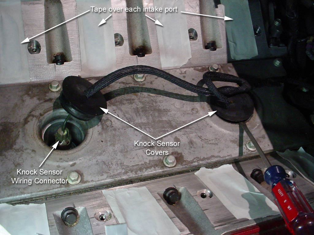
Now you can see the engine valley cover. The first thing we need to do is get ALL the dirt we can off the head surfaces around the intake ports. We don't want any of this falling into the ports, so be careful. A vacuum may help here, and then finish it off with some wet cloths and some degreaser making sure you wipe AWAY from the ports to keep it out of them. Once the head surfaces are clean, apply a piece of masking tape over each port to seal them up. This will help keep all the metal shavings out of the motor once we start dremeling the engine block in a little bit. Once you've taped over the 8 ports, pry up both of the black round plastic covers that are pressed into the valley cover using a flat head screw driver. The covers will allow the wire to slide through them so you can pull them out of the way a little bit. |

|
Under the round covers are the 2 knock sensors. As shown in the picture, either use heavy pressure with your fingers or LIGHT pressure with some pliers and squeeze the knock sensor wiring connector while pulling up. This will disconnect them. |
|
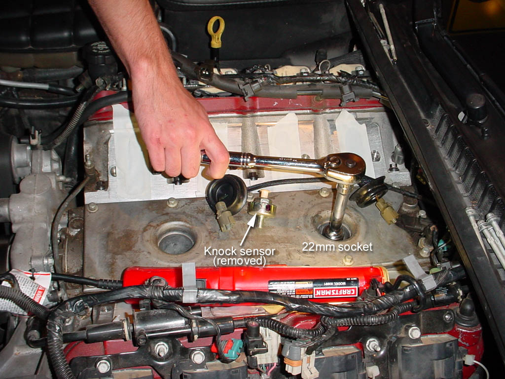
Using a 22mm (or 7/8" if you don't have a 22mm) socket and an extension, unbolt the knock sensors from the engine block and remove them. They are identical so it doesn't matter which is which. |
|
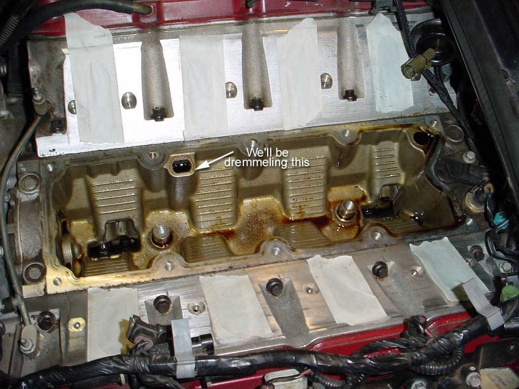
Next, using a 10mm socket, unbolt all 10 10mm bolts that hold the valley cover to the engine block. Once unbolted, use a flathead screwdriver to pry the edges up carefully. Once pried up, you should be able to lift the cover off the engine. There are some rubber grommets down inside each knock sensor well and they will probably cause some resistance when removing the cover. Now, we can see the engine valley! On the LS1 the valley is pretty much sealed up, except for a couple of areas. The most important part inside this valley is the aluminum block that is on the old style LS1 blocks (1997-2001'ish). It is labeled in this picture. If you do NOT have this piece, you can skip past all the next few steps about dremeling the engine, and go straight to putting on the new LS6 valley cover. |

|
You may be asking, why do we need to cut the block? Well, now that you have your stock LS1 valley cover off you can compare it to the new LS6 valley cover. Flip them over and look at the underside. As you can see, the LS6 valley cover has a large black oil separator box, which is where the new PCV system is going to pull its air from. This should be much better than the valve cover PCV system LS1's come with, as there is a large amount of oil flying around inside the valve covers. |

|
Before we start cutting, we need to protect the engine from getting metal bits in it. Place towels ALL over everything, except for the aluminum chunk we'll be removing (as shown in this picture). It may even help to stuff some paper towels into the 2 big holes in the engine before putting these towels down...you can't seal this up too good, so go crazy with this step. |

|
PUT ON YOUR SAFETY GOGGLES NOW! Now install a fiberglass reinforced cutting wheel on your dremel. Look inside the pit in the aluminum chunk and you'll see its about 3/4" deep. We need to chop the wall off this block all the way down so that its even with the bottom of the pit. It may help for you to mark a line on the aluminum about 3/4" down so you now where to cut. At first, I made my incision 1/2" down on the chunk, but that turned out not to be enough, so look at the photograph on the left and start cutting right about where I have marked with the black line. The dremel will work best if you crank it up to full speed, and try to keep the dremel VERY stable and still, just applying slight pressure to cut. This part should take 5-30 minutes depending on how comfortable you are with a dremel and how many fiberglass cutting wheels you have to change out (some wear down, some shatter). You should do the whole job in 3 cuts. One on the main wall 3/4" down from the lip, and then 2 going up the side walls (these may be easier if you have the 90 degree adapter for your dremel, which I didn't use) How far you go back with your cut on the sidewalls isn't that important, as its the wall closest to the center of the engine that causes the conflict with the LS6 valley cover. See the next picture to get a clearer picture of what I'm talking about. |

|
Once it is all said and done, this is approximately what the finished product should look like (except yours should look better now that I've told you how much to cut off from the start). Carefully remove all your towels and either using a vacuum or a wet rag make sure you clean ALL metal shavings out of the valley cover and surrounding areas. If you placed your towels right this cleanup step should be pretty easy. Once again, you can't make this too clean so go crazy if you are in doubt. |

|
MAKE SURE ALL TOWELS AND RAGS ARE OUT OF THE VALLEY! VERY IMPORTANT! If your new LS6 valley cover came with bolts, remove all 10 bolts. Lay the gasket in place in the valley, and then place the top onto the gasket making sure to align the knock sensor wells with the threaded bosses sticking out of the valley. Hand thread all 10 bolts just a few threads to make sure you got the gasket aligned properly (you can use a screwdriver in the bolt holes to align the gasket if needed). Once all 10 bolts are started, tighten them all down and torque them to 18 lb/ft. Next, hand thread in both knock sensors until they bottom out. Torque these to 11 lb/ft. Reconnect both wiring plugs, and slide the plastic connectors back in place. |

|
Now, since we've got a new PCV port on the LS6 valley cover, we don't need the stock LS1 PCV system. On the rear of the drivers side valve cover, part of the LS1 PCV hose plugs into a grommet. Using a flathead screwdriver, pry it out, and plug the grommet with the GM part 12568011 |

|
Next, on the rear of the passenger side valve cover there is a brass fitting with a rubber hose attached. Pull that off, and cap the brass fitting with a rubber cap. The bright red one that came with my LS6 cover is what I used. If for some odd reason your LS6 cover didn't come with one, any autoparts store will have one for a buck or two. You should need a 5/16" cap. |

|
Once this is done, you should be able to remove the whole PCV hose as one piece. If you are curious as to what this looks like, its the blue and yellow highlighted hoses in this picture to the left. The vent tube that runs from the front of the passenger valve cover to the throttle body remains as-is. |

|
Now we need to reinstall the intake manifold. It is mostly the reverse of the previous steps. Re-insert the 2 or 4 rear long intake manifold bolts back into the manifold (remember, the drivers side rear of the manifold had a metal bracket that is held in place by the rear 2 bolts on that side) and while holding them up, slide the manifold back into place. Reconnect the rear sensor, and snake the big brake booster line back into place and reconnect it to the booster. Now reconnect the small vacuum line that goes to the back of the intake manifold. Once everything in the back is reconnected, slide the manifold into place until those rear 2 or 4 bolts are perfectly lined up and drop down into their holes. MAKE SURE you don't catch any small vacuum lines underneath the intake manifold before you bolt it down. I forgot to check on one install and the pinched vacuum line left me without A/C controls. Having to go back in and replace vacuum line because of a stupid mistake sucks. Now, hand thread in all 10 of the bolts as far as they'll go. |

|
Once all 10 intake manifold bolts are hand threaded as far as they'll go, tighten them down with a wrench and then torque in the order shown in the picture on the left. You need to torque these down in a 2-pass fashion..the first pass, tighten to 44 INCH-lbs, then, on the 2nd pass torque them to 89 INCH-lbs. Again, note those specs are in INCH lbs. If you don't have an inch pounds torque wrench, just tighten the bolts hand tight...its only about 7 ftlbs of torque on that final pass and the intake seals with rubber gaskets so its doesn't need much pressure at all to seal.
On an f-body, reconnect the throttle cable bracket and tighten the 2 bolts to 89inch pounds. Reconnect the 8 fuel injector wires, reconnect the fuel vapor line to the drivers front side of the intake manifold, reconnect any throttle body sensors, throttle cables, MAF, and air intake setup. |

|
Now, the intake manifold and air intake is all reinstalled. Your engine is totally complete, EXCEPT ONE THING. The new PCV hose. Since we removed the stock hose, we need to re-install some sort of PCV setup. The PCV valve will pull off the end of the stock PCV hoses. We'll need to reuse this for the new setup. Once its pulled off, we'll need some way to join some 5/16" rubber fuel line to it, which means we need a coupler. You either need to buy a 3/8" coupler from the autostore, or use the dremel to cut off a 1.5" long section of the stock plastic pipe to use as a coupler. Once you've got the pcv removed, and a 1.5" piece of plastic coupler, you should be able to use that to attach a 10" piece of 5/16" rubber fuel line to the PCV valve, as shown in the picture. |

|
Now, push the PCV valve tip into the intake manifold like it was stock, then connect the rubber fuel line end to the new PCV port our valley cover had. The fuel line should make a little loop out in front of the passenger side cylinder head nice and neatly. This is very similar to the PCV pipe that comes with the LS6. |

|
That's it! Now check for any loose connectors, hoses, etc. Read over the install and make sure you did everything. If you have fuel rail covers, pop them back on. From this point on, you should enjoy a little less oil consumption from your LS1. |